i.c.sens Mapathon
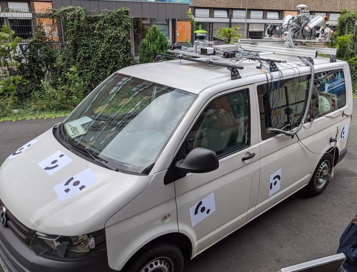 One of the vans used during our measurement campaign
To gather data for the projects of all nine PhD students of the Research Training Group “Integrity and Collaboration in Dynamic Sensor Networks” (i.c.sens) we regularly conduct large-scale measurement campaigns which are denoted as mapathons. After being part of two mapathons as a PhD student in the past, I participated in the third mapathon as the i.c.sens Postdoc. This was the first mapathon for the second cohort of PhD students and took place over 4 days from Aug 24 to Aug 27 in the Nordstadt in Hannover.
The planning and the preparations for our measurement campaign already started about two months before the actual experiment. Many of the sensor and software setups developed by the first cohort of PhD students were still available and could therefore be used. However, there were also some novel requirements of the new PhD students which demanded some of the setups to be adapted. In total, we equipped three vans with various sensors and put special markers onto them to allow an easy detection in camera images. Besides, an UAV (Unmanned Aerial Vehicle) was equipped with stereo cameras to provide a top-view of one intersection at which the three vehicles met. In the following, I want to give an overview of the sensors attached to the three vehicle:
IKG van
The IKG van, which can be seen in the picture above, was equipped with the following sensors:
- Riegl VMX-250 Mobile Mapping System: A commercially available system that consists of two laser scanners, a camera system and a localization unit.
- Front-looking stereo camera setup consisting of two PointGrey Grasshopper cameras.
- MicroStrain 3DM-GQ4-45 Inertial Measurement Unit (IMU).
- Cepton Vista-P60: a long range, high resolution and frictionless LiDAR.
- Two Velodyne LiDAR Puck VLP-16: one on the car roof scanning horizontally and one on the trailer coupling scanning vertically.
- One GNSS antenna + receiver.
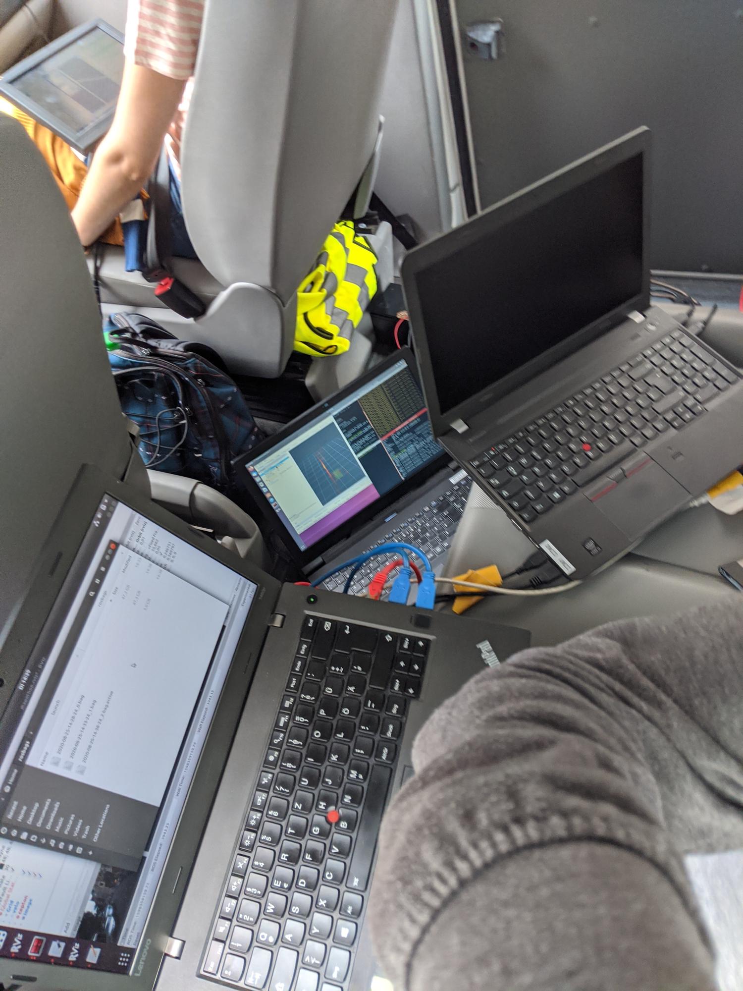
The IKG van was the most equipped van and thus required the most laptops and people operating the laptops and sensors. During the measurement drive, I took responsibility for a total of three laptops to which the sensors mentioned above were connected, with the exception of the Mobile Mapping System. All of the laptops ran Ubuntu as the operating system, and the Robot Operating System (ROS) was used to control the sensors and record their data. Some pictures of my workplace can be seen below.

IfE van
The IfE van was equipped with the following sensors:
- Front-looking stereo camera setup consisting of two PointGrey Grasshopper cameras.
- iMAR Inertial Measurement Unit (IMU).
- Multiple GNSS antennas + receivers.
The IfE van was equipped with the most GNSS antennas and different receivers to study the localization of autonomous vehicles using GNSS information. To compute tightly coupled positioning information, a high-grade IMU was employed.
GIH van
The GIH van was equipped with the following sensors:
- Front-looking stereo camera setup consisting of two PointGrey Grasshopper cameras.
- One GNSS antenna + receiver.
The GIH van was used to obtain a dynamic sensor network with at least three nodes and to have a third stereo camera setup.
Setup of the sensor platforms
The sensor platforms were either reused from the mapathons of the first cohort, slightly adapted or completely rebuilt. Since aluminum profiles had proven themselves during our first mapathon, the PhD students in the second cycle also decided to use them. These aluminum profiles made it possible to mount the sensors rigidly without being too heavy to carry them inside for calibration purposes.
Calibration of the sensor platforms
To compute the relative transformation between all sensors on the platforms, the platforms were carried into our so-called 3D lab. Here, a Leica Absolute Tracker AT960 was used to measure reference points on the sensor housing, which then allowed to compute the rigid body transformation between sensor coordinate systems.
After the sensor platforms had been mounted onto the vans, we moved the laser tracker outside to also determine the transformation between the markers on the cars and the sensor platforms.
Synchronization of all sensors
All sensors were synchronized to GPS time. Since all sensors except for the cameras either directly contained a GNSS receiver or allowed to connect one, we did not have to worry about the synchronization of these sensors. For example, the Velodyne and the Cepton LiDARs are compatible with commercially available GNSS receivers. After connecting these receivers to the sensors, an accurate timestamp is assigned to every single measured point.
To also synchronize the stereo cameras to GPS time, we employed the synchronization box that I had developed for the mapathons of the first cohort. The synchronization box contains a Raspberry Pi, which is connected to a simple GNSS receiver to synchronize its own internal clock to GPS time. Now, the idea is to let the Raspberry Pi record a timestamp whenever the cameras take an image.
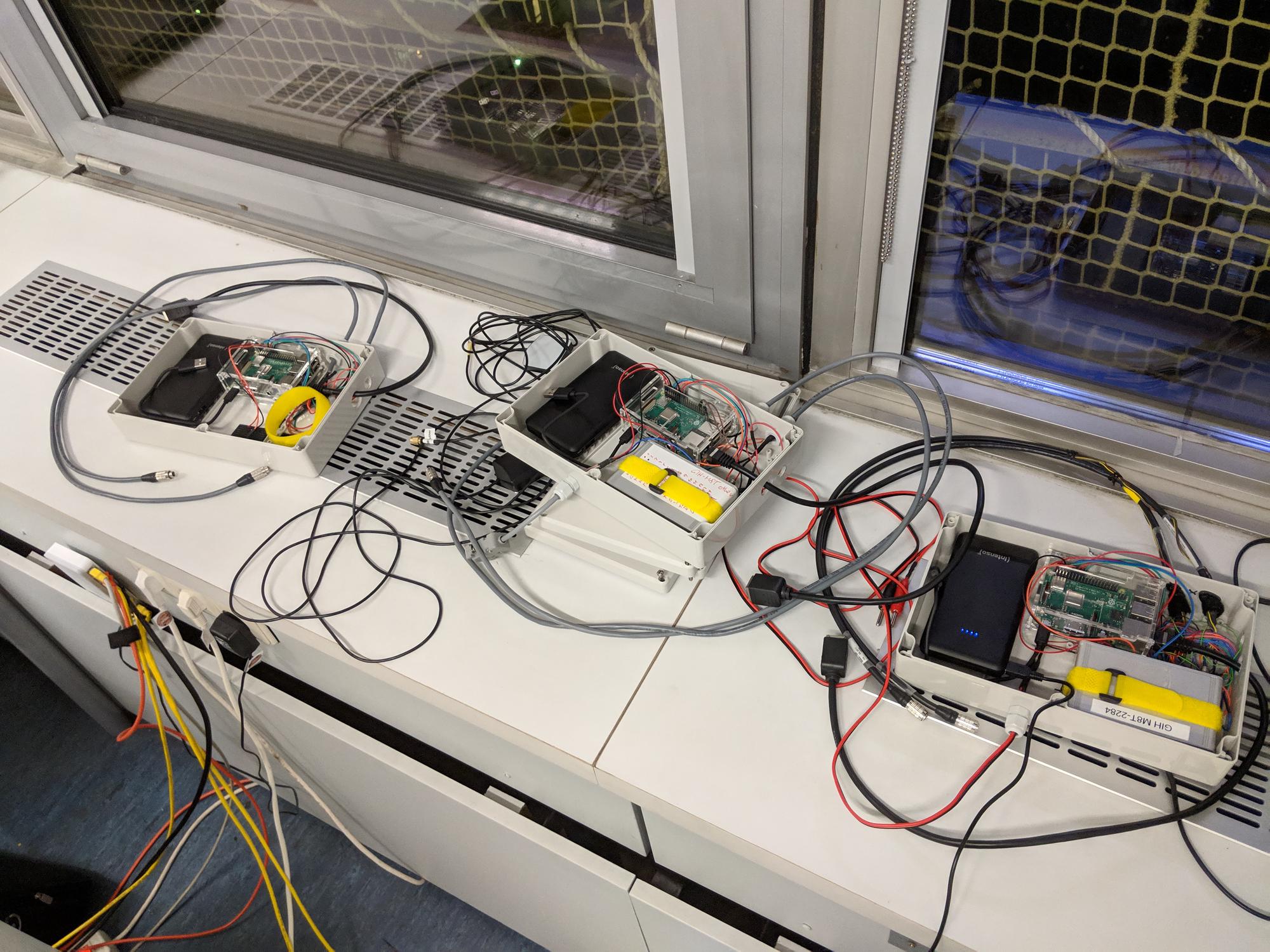
Fortunately, every camera has a GPIO connector which, among other things, offers a rising edge whenever the camera starts the imaging process. These electrical pulses are usually used to synchronize the image acquisition of the left and right camera of a stereo pair. We also used these electrical pulses for this purpose, but additionally wired them into the synchronization box in order to detect the rising edge using the Raspberry Pi, which then recorded a timestamp. Since the Raspberry Pi is synchronized to GPS time as explained above, this timestamp is the GPS timestamp of the corresponding stereo image pair.
My role in the mapathon
Since I had already taken part in two mapathons during my time as a PhD student, I supported the new PhD students from the first planning to the actual measurement drives.
While planning, I was able to guide the PhD students not to make the same mistakes we made during our first mapathon. In addition, I was able to explain the necessary steps to them and which tasks had to be solved. Besides, I showed them the solutions (for example the synchronization box) we had developed during our first mapathon and which could be directly employed for the upcoming mapathon.
During the mapathon, I operated most of the sensors of the IKG van as explained and shown above. Besides, I was able to help with technical or organizational issues, as I already had this experience from our previous measurement drives.
Raphael Voges
Doctor in Robotics
My research interests include error modeling, sensor fusion, SLAM, state estimation and AI in the context of autonomous driving.